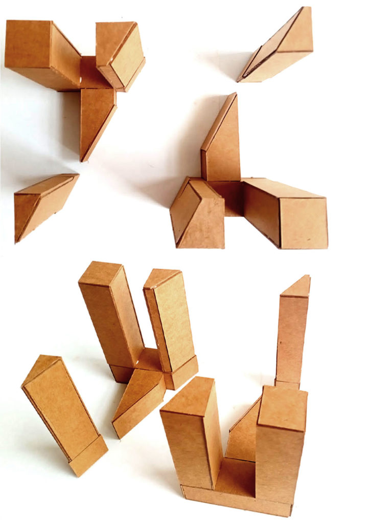
PRISMATIC MODELS & ORTHOGRAPHIC DRAWINGS
the plan, the section and the model, each present diverse and unique dimensions of the architecture that we are trying to develop; while the model takes us closer to the spatial and formal experiences, the plan presents the spatial relationships with a simultaneity that no other medium can offer, and the section reveals not only the volumetric slice across various levels, but also helps us understand the methods of making our architecture…
Siddharth Singh
INTENT
VSR, scheduled as the beginning of each day, is intended as exercises in centering ourselves: bringing our mind & body together through an undisturbed engagement of an hour in sketching/ drawing and making models.

Nainsi 
Maitri 
Parth 
Netri 
Maitri 
Aanchal 
Eyal 
Parth
TEACHING-LEARNING STRATEGIES
This brief focuses on making models and orthographic drawings of geometric prisms.
Students need to first create the model for each exercise and follow it up with its plans, elevations and sections.
The process will be interspersed with conversations with peers during group interaction through the week and tutor comments on G.Classroom.
Work created for the scheduled hour every day is to be submitted as PDF as well as posted on the assigned Miro board by 0930 hrs on the same day – before the studio session with the tutors’ begins.
Regular update of the Reflective Blog is a mandatory requirement of the studio. You may choose to blog daily or weekly or with respect to briefs or exercises; however, stick to a chosen schedule for at least 4 weeks or through a module.
Reference outputs shared in the brief are only suggestive.
LEARNING OUTCOMES
The 1:1 scale manual drawings and models to be created in response to the five exercises scheduled for this fortnight-long brief will help in developing the mental abilities of translating descriptive text to 3D forms and orthographic projection.
Besides documenting the processes and recording its highs & lows, it’s necessary to reflect on these aspects and note the consequent deliberations in the Studio Blog.
EXERCISES & ASSESSMENT ELEMENTS or DELIVERABLES
MODELS
Medium: Cartridge Paper or Cardboard
ORTHOGRAPHIC DRAWINGS
Format: A1; Medium: Ink or Graphite – Manually Drafted on Cartridge or Freehand on Graph Paper
Configuration-1
A Hexagonal prism of side 15 cm and height 30 cm is placed to the west of a Pentagonal Prism of side 10 cm and height 20 cm. The two models are placed on the same central axis with a distance of 5 cm between them, with the vertices of the Hexagon aligned to north-south axis and vertex of pentagon aligned to east. One face each of the Hexagon and Pentagon are aligned to each other.
A sectional plane sloping downwards from the east to west, making a 30O angle with the top face of the prism, cuts through both the objects.
Draft the Orthographic projections of the resulting forms.
Configuration-2
A right angled Trapezoidal prism with a base and height of 20 cm and top side of length of 10 cm is placed with its perpendicular plane facing west.
A sectional plane sloping downwards from the western top edge makes a 60O with the top face of the prism and cuts the object.
A rhomboid emerges from the cut face, with a height equivalent to the length of the face resulting from the cut.
Draft the Orthographic projections of the resulting forms.
Configuration-3
A Cylinder of radius 6 cm and height 15 cm is placed on ground. The South-East Quadrant is cut and slid out towards the east by a distance of 6 cm and further 1cm towards the south from its original position.
A sectional plane slopes downwards from the western edges of the cylinder, making a 30O with the top edge of the cylinder. This plane cuts through the cylinder and the displaced quadrant.
Draft the Orthographic projections of the resulting forms.
Configuration-4
Three identical cuboids of dimensions; length= 5cm, breadth=5cm and height=15cm are placed in such a way that one of the rectangular faces of the cuboid is placed on the ground.
All the 3 cuboids are placed orthogonally to each other in a way that when the composition is viewed from the western side, the rectangular faces of one of the cuboids is placed in between the square faces of the other two cuboids and only one rectangular face is seen from either the northern or southern side.
4 identical cuboids of dimensions’ length= 5 cm, breadth=5 cm and height= 18 cm are placed atop each end of the parallel cuboids. These 4 cuboids are placed in such a way that the height is perpendicular to the composition on which these cuboids are placed.
A sectional plane perpendicular to the ground plane passes through the South-West vertex of the cuboid making a 30O anglewith the west face of the South-West cube.
Draw the Orthographic projections for both the resultant sections.
Notes:
- All configurations are to be created in the given order
- Cardboard cuts & pasting of parts should be clean in the model; explore half cuts where possible
- Besides the plan from above, cut another plan at mid height of each configurations as well as two perpendicular sections through the medians (assume sections planes passing through mid-points) of each prismatic configuration
- Consider a wall thickness of 1CM in the plans & sections showing cut planes of the configurations
- All the drawings should be neatly drafted with relevant line-weights & poché and appropriately labelled. The Guidelines/ Construction lines etc. should be visible in the drawings.

 malkum